¡Descarga Exercise about isolated devices y más Tesis en PDF de Física solo en Docsity!
Solutions to Chapter 1 Exercise Problems
Problem 1.
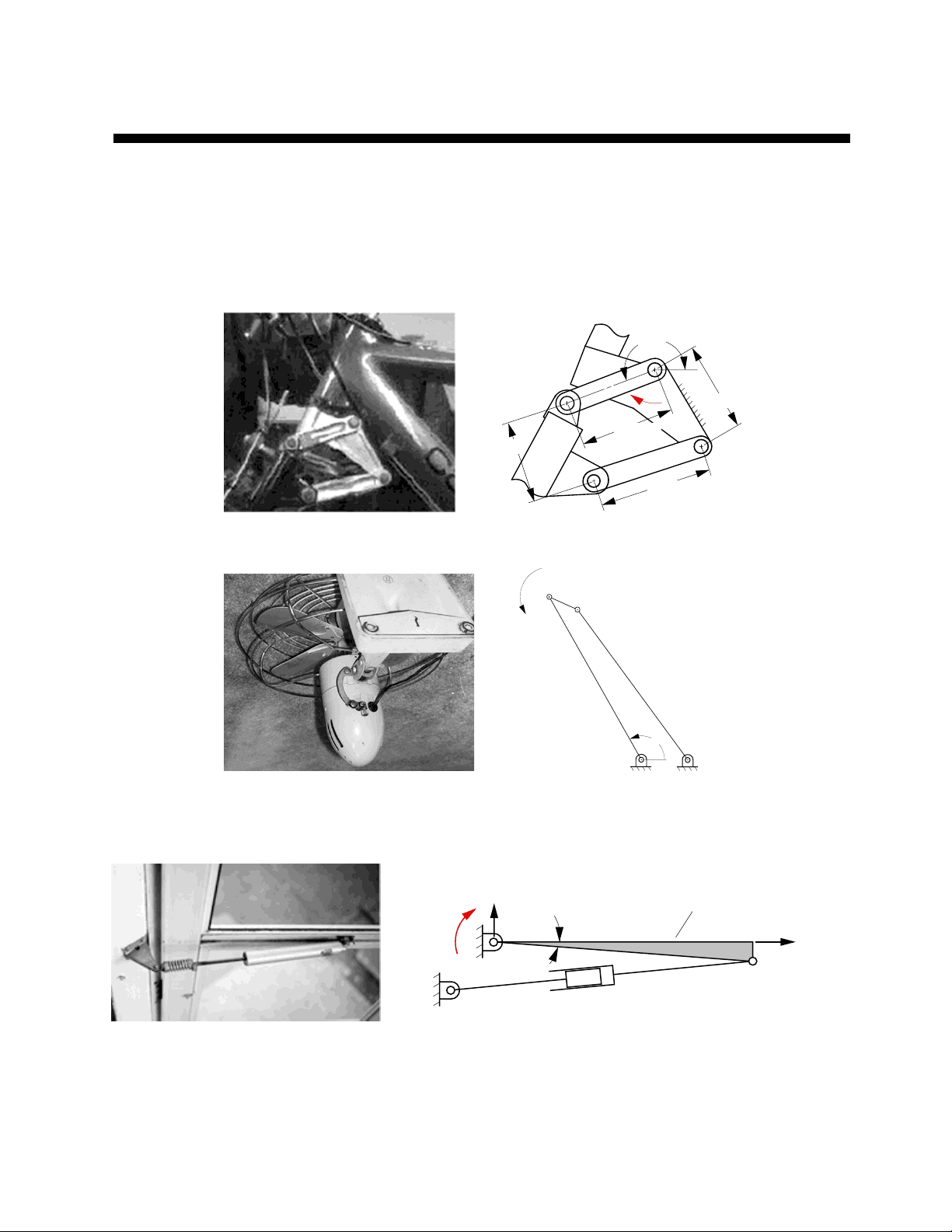
Find a mechanism as an isolated device or in a machine and make a realistic sketch of the mechanism. Then make a freehand sketch of the kinematic schematics for the mechanism chosen.
Typical examples of solutions for this problem are given in the problem definitions of Chapter 3. Some examples are:
2
4
1 3
A
D C
B
1.88"
2.22"
201 ˚
1.55"
1.64"
ω 2
Bicycle suspension
A
B C
D
θ
2
3
4
(^2) ω 3
Oscillating fan
ω 2
A B
C
D
2
3 4
6 ˚ Y Door
X
Door closing linkage
Cabinet hinges use various types of linkages for the folding mechanism. Identify three types of cabinet hinges and make a freehand sketch of the kinematic mechanism used.
There are a large number of mechanisms that are used to obtain various types of hinge motions. Below are three of them. The first is a 6-bar Watt’s linkage used for chest lids. The hinge guides the chest lid such that no part of the lid crosses the plane of the back of the chest. The second example is a four bar linkage that guides the door from the open to closed position. The hinge is basically hidden when the door is closed. The third uses a 6-bar Watt’s linkage with a slider. The lid glides about the back corner of the box.
Solution
A
B
C
Water Pump
1
2
3
4
5
6
Casement window mechanism
Folding Chair
Linkages are often used to guide devices such as computer keyboards in and out of cabinets. Find three such devices, and make a freehand sketch of the kinematic mechanisms used for the devices.
Typewriter desk linkage
Under drawer swing up mechanism
Overhead bin hinge
Problem 1.
Fourbar linkages are used in common devices around the home and businesses. Locate six such devices and make a freehand sketch of each device and describe its function.
Solution: Sample examples are given in the following:
Tree trimmer. The fourbar linkage is a double lever mechanism used to increase the mechanical advantage
Vicegrips. The fourbar linkage is a toggle mechanism
Calculate the mobility, or number of degrees of freedom, of each of the mechanisms in Problem 1.3.
A
B
C
n = (^4)
j (^) = 4
M (^) = 3(n (^) − j (^) − 1) + f (^) i i= 1
j
Mobility = 1
= 3(4^ − 4 − 1)^ + 4 = −^3 + 4 = 1
Water Pump
1
2
3
4
5
6
= 3(N (^) L − N (^) J − 1) + f (^) i i= 1
j
Mobility = 1
Casement window mechanism
Folding Chair
n = (^3)
j = (^3)
= 3( ) + f (^) i i= 1
Mobility = 1
f (^) i = 2)
Arbitrarily pick link 1 as the frame
pin-in-slot joint ( M n^ −^ j^ −^1
n
j
M
j
What are the number of members, number of joints, and mobility of each of the planar linkages shown below?
(a) (b)^ (c)
(a)
(b)
(c)
1
2 3
4
fi i= 1
j
M = + fi i= 1
4 x 1 = 4
fi i= 1
j
∑ = 8 x 1 = 8
= 3(7^ − 8 − 1)^ + 8 = −^6 + 8 = 2
fi i= 1
∑ = 10^ x 1 =^10
Mobility = 1
Mobility = 2
Mobility = 1
n
j
j 3( (^) n − j− 1 )
n
j
M = + f (^) i i= 1
j 3( n − j− 1 )
M = + f (^) i i= 1
j 3( n − j− 1 )
n
j
j
Determine the mobility and the number of idle degrees of freedom of each of the planar linkages shown below. Show the equations used and identify the input and output links assumed when determining your answers.
(a) (b)^ (c)
(a)
1
3 2
4
5
6 7
8
9
(b)
1
2
3
4
6 5
7
(c)
Idle DOF = 0
n = 9
j = 12
M = 3(n − j − 1) + f (^) i i= 1
j
Mobility = 0
Idle DOF = 0
n = 7
j = 9
M = 3(n − j −1) + f (^) i i= 1
j
Mobility = 0
Idle DOF = 0
n = 10
j = 12
M = 3(n − j − 1) + f (^) i i= 1
j
Mobility = 3 1
2
(^3 4 )
6
7 8
9 10
= 3(9^ − 12 −1)^ + 12 = −^12 + 12 = 0
= 3(7^ − 9 −1)^ + 9 = −^9 + 9 = 0
= 3(10^ − 12 −1)^ + 12 = −^9 + 12 = 3
Determine the mobility and the number of idle degrees of freedom associated with the mechanism. Show the equations used and identify any assumptions made when determining your answers.
2
3 4
1
2
3 4
Idle DOF = 1
n = 4
j = 4
M =^ 3(n − j − 1) + f (^) i i= 1
j
Mobility = 1
= 3(4^ − 4 −1)^ + 4 = −^3 + 4 = 1
Determine the mobility of each of the planar linkages shown below. Show the equations used to determine your answers.
(a) (b)
Piston 1
Piston 2
Bucket
Hydraulic Cylinder
Hydraulic Cylinder
n (^) = (^9)
j (^) = (^11)
fi i= 1
j
M = 3(n^ − j^ − 1)^ + fi i= 1
j
11 x 1 =
(a)
Mobility = 2
n = (^11)
j =^14
fi i= 1
j
M = 3(n − j − 1) + f (^) i i = 1
j
14 x 1 = 14
(b)
Mobility = 2
Determine the mobility and the number of idle degrees of freedom of each of the planar linkages shown below. Show the equations used to determine your answers.
(a) (b) (c)
(c)
(b)
Idle DOF = 0
n = 5
j = 6
M = 3(n − j − 1) + f (^) i i= 1
j
Mobility = 1
Idle DOF = 0
n = 7
j = 9
M = 3(n − j − 1) + f (^) i i= 1
j
Mobility = 0
Idle DOF = 0
n = 12
j = 15
M = 3(n − j − 1) + f (^) i i= 1
j
Mobility = 3
1
2 3 4 5 6 7 1
2
3
4
5
6 7 8
9 (^10 )
12
= 3(5^ − 6 − 1)^ + 7 = −^6 + 7 = 1
= 3(7^ − 9 −1)^ + 9 = −^9 + 9 = 0
= 3(12^ − 15 −1)^ + 15 = −^12 + 15 = 3
1 2
3
4
5
(a)
Determine the mobility and the number of idle degrees of freedom of each of the planar linkages shown below. Show the equations used to determine your answers.
(a) (b) (c)
(c)
(b)
(a) Idle DOF = 0
n = 12
j = 15
M = 3(n − j − 1) + f (^) i i= 1
j
Mobility = 3
Idle DOF = 0
n = 10
j = 11
M = 3(n − j − 1) + f (^) i i= 1
j
Mobility = 5
Idle DOF = 0
n = 10
j = 13
M = 3(n − j − 1) + f (^) i i= 1
j
Mobility = 1
1
2
3
4
5
6 7
8
9
(^10 ) 12
1
2
3 4
5
6 7
8
9
10
1
2
3 4
5
6
7
8
9 10
= 3(12^ − 15 −1)^ + 15 = −^12 + 15 = 3
= 3(10^ − 11 −1)^ + 11 = −^6 + 11 = 5
= 3(10^ − 13 − 1)^ + 13 = −^12 + 13 = 1
Determine the mobility and the number of idle degrees of freedom associated with each mechanism. Show the equations used and identify any assumptions made when determining your answers.
Pin in Slot
(a) (b) (c)
Pin-in-Slot Joint Slider
(d) (e)
Cam joint
Sliders
Rolling joints