1
ECE 491
Laboratory 4 – RS-232 Serial Data Transmission
September 21, 2007
Goals
• To learn about the details of asynchronous data communication.
• To develop a simple-register transfer level design in Verilog that implements RS-
232 asynchronous data transmission.
• To build a testbench that verifies the operation of your design.
Requirements
You will develop an FPGA-based Asynchronous Serial Transmitter that meets the
following requirements:
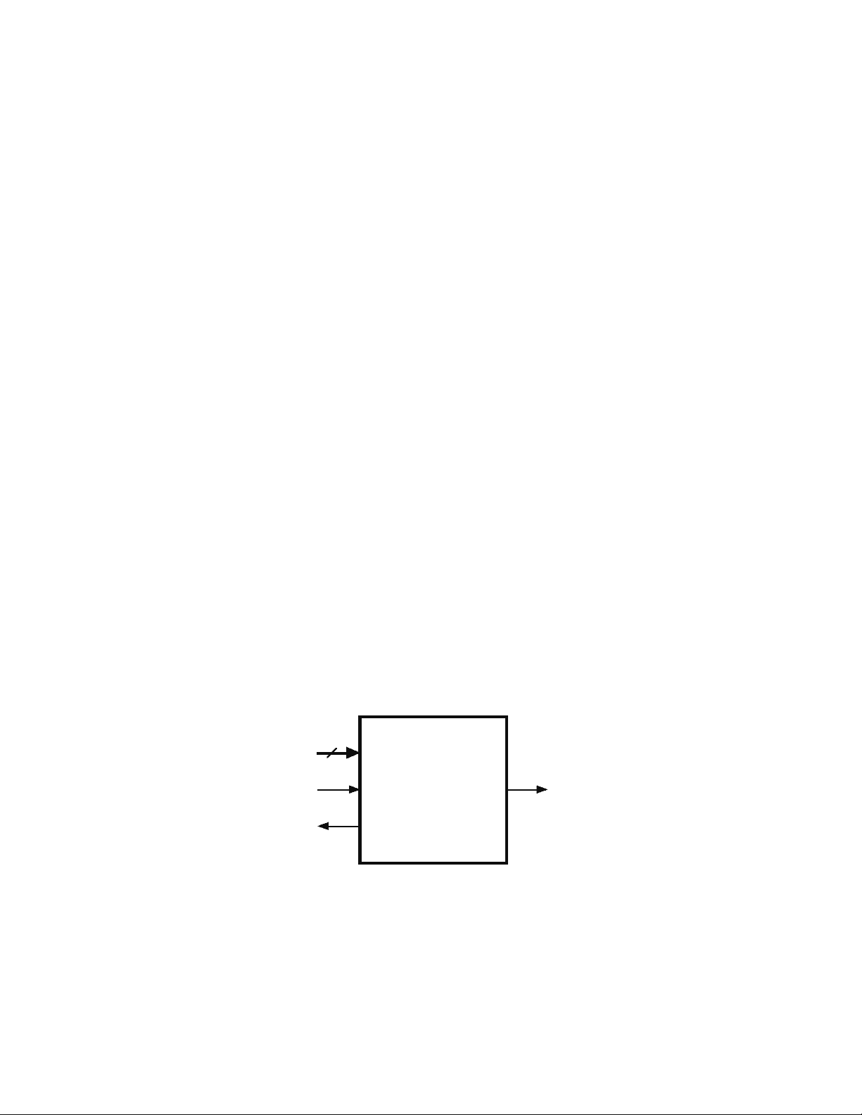
1. The transmitter will include an 8-bit data input, a 1-bit start input, and 1-bit outputs
txd and rdy, as shown below. When start is asserted, the data input should be
sampled and transmitted one bit at a time beginning with a “start bit” and finishing
with a single “stop bit” (see the “Background” section).
2. The transmitter design must be parameterized so that it can be configured to operate
at different Baud rates (9600 baud default).
3. The design must be verified using a self-checking testbench. This tesbench must test
the transmission of several different byte values, including 8’b01010101,
8’b00110011, and 8’b00001111. In addition, it must check that transmission
occurs correctly both when successive bytes transmit immediately and when they are
separated by several clock cycles. Your testbench will use the $display system
task to print out any errors which are found. In addition, it will print a message at
the end indicating that it completed and then pause simulation using the $stop
system task.
4. All Verilog code must follow the Coding Guidelines discussed in class.
DATA
START
RDY
TxD
Transmitter
8
Deliverables
1. Demonstration to Lab Instructor of successfully operating design transmitting
characters to a PC running HyperTerminal.
2. A short technical memorandum which describes (a) what was done, (b) what you
learned, and (c) what difficulties you encountered. Include a block diagram of your
design showing its major components.