Download Mobile phone systems and more Study Guides, Projects, Research Computer Systems Networking and Telecommunications in PDF only on Docsity!
Introduction to Mobile Telephone
Systems
1G, 2G, 2.5G, and 3G Wireless Technologies and Services
Lawrence Harte
Excerpted From:
Wireless Systems
With Updated Information ALTHOS Publishing
1st Generation (1G) Analog Cellular
Mobile Telephone System
3rd Generation (3G) Broadband Digital
Subscriber Identity Module (SIM) Card
2nd Edition
ALTHOS Publishing
Copyright © 2006 by the ALTHOS Publishing Inc. All rights reserved. Produced in the United States of America. Except as permitted under the United States Copyright Act of 1976, no part of this publication may be reproduced or distributed in any form or by any means, or stored in a database or retrieval system, without prior written permission of the publisher.
ISBN: 1-932813-93-
All trademarks are trademarks of their respective owners. We use names to assist in the explanation or description of information to the benefit of the trademark owner and ALTHOS publishing does not have intentions for the infringement of any trademark.
ALTHOS electronic books (ebooks) and images are available for use in educational, promo- tional materials, training programs, and other uses. For more information about using ALTHOS ebooks and images, please contact us at info@Althos.com or (919) 557-
Terms of Use
This is a copyrighted work and ALTHOS Publishing Inc. (ALTHOS) and its licensors reserve all rights in and to the work. This work may be sued for your own noncommercial and per- sonal use; any other use of the work is strictly prohibited. Use of this work is subject to the Copyright Act of 1976, and in addition, this work is subject to these additional terms, except as permitted under the and the right to store and retrieve one copy of the work, you may not disassemble, decompile, copy or reproduce, reverse engineer, alter or modify, develop deriva- tive works based upon these contents, transfer, distribute, publish, sell, or sublicense this work or any part of it without ALTHOS prior consent. Your right to use the work may be ter- minated if you fail to comply with these terms.
ALTHOS AND ITS LICENSORS MAKE NO WARRANTIES OR GUARANTEES OF THE ACCURACY, SUFFICIENCY OR COMPLETENESS OF THIS WORK NOR THE RESULTS THAT MAY BE OBTAINED FROM THE USE OF MATERIALS CONTAINED WITHIN THE WORK. APDG DISCLAIMS ANY WARRANTY, EXPRESS OR IMPLIED, INCLUDING BUT NOT LIMITED TO IMPLIED WARRANTIES OF MERCHANTABILITY OR FITNESS FOR A PARTICULAR PURPOSE.
ALTHOS and its licensors does warrant and guarantee that the information contained with- in shall be usable by the purchaser of this material and the limitation of liability shall be lim- ited to the replacement of the media or refund of the purchase price of the work.
ALTHOS and its licensors shall not be liable to you or anyone else for any inaccuracy, error or omission, regardless of cause, in the work or for any damages resulting there from. ALTHOS and/or its licensors shall not be liable for any damages including incidental, indi- rect, punitive, special, consequential or similar types of damages that may result from the attempted use or operation of the work.
-ii-
Copyright ©, 2006, ALTHOS, Inc
-iv-
Copyright ©, 2006, ALTHOS, Inc
-v-
Copyright ©, 2006, ALTHOS, Inc
SERVING GENERAL PACKET R ADIO SERVICE SUPPORT NODE (SGSN)
PACKET DIGITAL CELLULAR SYSTEMS (GENERATION 2.5)
-vii-
- MOBILE TECHNOLOGIES Table of Contents
- C ELLULAR FREQUENCY R EUSE
- HANDOVER
- SPEECH C OMPRESSION
- MODULATION TYPES
- A CCESS MULTIPLEXING
- Frequency Division Multiple Access (FDMA).
- Time Division Multiple Access (TDMA).
- Code Division Multiple Access (CDMA).
- Spatial Division Multiple Access (SDMA).
- P ACKET DATA
- MOBILE DEVICES
- SUBSCRIBER I DENTITY MODULE (SIM)
- PCMCIA A IR C ARDS
- E MBEDDED R ADIO MODULES
- MOBILE TELEPHONES
- E XTERNAL R ADIO MODEMS
- MOBILE SYSTEMS
- B ASE STATIONS
- R ADIO A NTENNA TOWERS
- C OMMUNICATION LINKS
- MOBILE SWITCHING C ENTER (MSC)
- A UTHENTICATION , AUTHORIZATION , AND A CCOUNTING (AAA)
- I NTERWORKING FUNCTION (IWF)
- MESSAGE C ENTER (MC)
- GATEWAY GPRS SUPPORT NODE (GGSN) Copyright ©, 2006, ALTHOS, Inc
- B ASE STATION C ONTROLLER (BSC)
- V OICE MESSAGE SYSTEM (VMS)
- PUBLIC SWITCHED TELEPHONE NETWORK (PSTN)
- PUBLIC PACKET DATA NETWORK (PPDN)
- NETWORK DATABASES
- Home Location Register (HLR).
- Visitor Location Register (VLR).
- Equipment Identity Register (EIR).
- Billing Center (BC).
- Authentication Centre (AuC).
- Number Portability Database (NPDB).
- IP B ACKBONE NETWORK
- MOBILE SYSTEM OPERATION
- I NITIALIZATION
- I DLE
- A CCESS C ONTROL AND I NITIAL A SSIGNMENT
- C ONNECTED MODE
- P ACKET DATA SCHEDULING A LGORITHM
- R EGISTRATION
- ANALOG SYSTEMS (1ST GENERATION)
- A DVANCED MOBILE PHONE SERVICE (AMPS)
- TOTAL A CCESS C OMMUNICATION SYSTEM (TACS)
- NORDIC MOBILE TELEPHONE (NMT)
- NARROWBAND AMPS (NAMPS)
- J APANESE MOBILE C ELLULAR SYSTEM (MCS)
- CNET
- MATS-E
- DIGITAL CELLULAR SYSTEMS (2ND GENERATION)
- GLOBAL SYSTEM FOR MOBILE C OMMUNICATION (GSM)
- NORTH A MERICAN TDMA (IS-136 TDMA)
- E XTENDED TDMA (E-TDMA)TM
- I NTEGRATED DISPATCH E NHANCED NETWORK ( I DEN)
- C ODE DIVISION MULTIPLE A CCESS (IS-95 CDMA)
- J APANESE PERSONAL DIGITAL C ELLULAR (PDC)
- GENERAL PACKET R ADIO SERVICE (GPRS)
- E NHANCED DATA R ATES FOR GLOBAL E VOLUTION (EDGE)
- CDMA2000™ 1 X RTT
- E VOLUTION DATA ONLY (1 X EVDO)
- E VOLUTION DATA AND V OICE (1 X EVDV)
- GENERATION) WIDEBAND DIGITAL CELLULAR SYSTEMS (3RD
- W IDEBAND C ODE DIVISION MULTIPLE A CCESS (WCDMA)
- C ODE DIVISION MULTIPLE A CCESS 2000 (CDMA2000)
- T IME DIVISION SYNCHRONOUS CDMA (TD-SCDMA)
- FOURTH GENERATION (4G) NETWORKS
- MOBILE SERVICES
- V OICE SERVICES
- Circuit Switched Voice.
- Push to Talk (PTT).
- MESSAGING
- DATA SERVICE
- Circuit Switched Data.
- Packet Switched Data.
- LOCATION B ASED SERVICES (LBS)
- MULTICAST SERVICES
QUALITY OF SERVICE (QOS).............................. 70
Conversation Class.................................. Streaming Class.................................... Interactive Class.................................... Background Class...................................
-viii-
Copyright ©, 2006, ALTHOS, Inc
tomers active in its system). The switching system in the MSC is coordinat- ed by call processing software that receives requests for service and process- es the steps to setup and maintain connections through the MSC to desti- nation communication devices such as to other mobile telephones or to tele- phones that are connected to the public telephone network.
Mobile Technologies
The key technologies used in cellular mobile radio include cellular frequen- cy reuse, handover, digital modulation, access technologies and packet data transmission.
-2-
Copyright ©, 2006, ALTHOS, Inc
Introduction to Mobile Telephone Systems, 2nd Edition
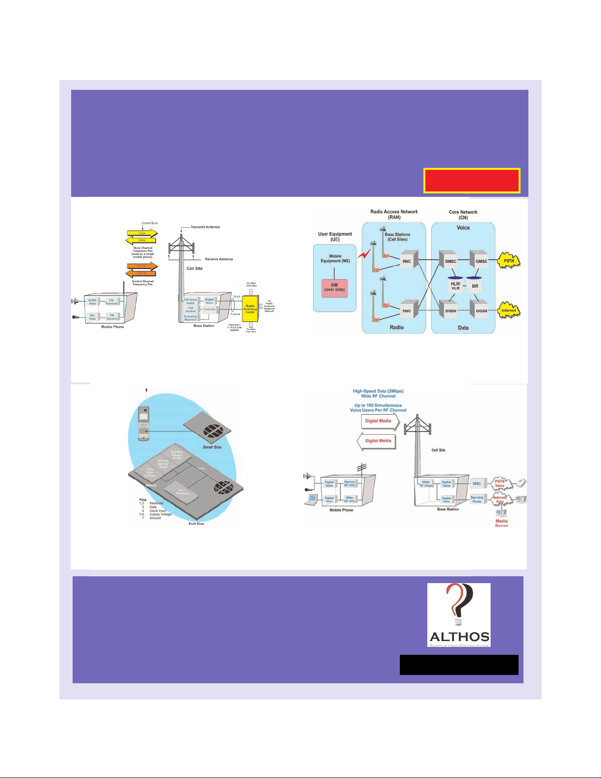
Figure 1.1, Basic Cellular System
Cellular Frequency Reuse
Frequency reuse is the process of using the same radio frequencies on radio transmitter sites within a geographic area that are separated by sufficient distance to cause minimal interference with each other. Frequency reuse allows for a dramatic increase in the number of customers that can be served (capacity) within a geographic area on a limited amount of radio spectrum (limited number of radio channels).
In early mobile radio telephone systems, one high-power transmitter served a large geographic area with a limited number of radio channels. Because each radio channel requires a certain frequency bandwidth (radio spectrum) and there is a very limited amount of radio spectrum available, this dra- matically limits the number of radio channels that keeps the low serving capacity of such systems. For example, in 1976, New York City had only 12 radio channels to support 545 customers and a two-year long waiting list of typically 3,700 [1].
To conserve the limited amount of radio spectrum (maximum number of available radio channels), the cellular system concept was developed. Cellular systems allow reuse of the same channel frequencies many times within a geographic coverage area. The technique (called frequency reuse) makes it possible for a system to provide service to more customers (called system capacity) by reusing the channels that are available in a geographic area. In large systems such as the systems operating in New York City and Los Angeles, radio channel frequencies may be reused over 300 times. As systems start to become overloaded with many users, to increase capacity, the system can expand by adding more radio channels to the base station or by adding more cell cites with smaller coverage areas.
To minimize interference in this way, cellular system planners position the cell sites that use the same radio channel farthest away from each other. The distances between sites are initially planned by general RF signal prop- agation rules. It is difficult to account for enough propagation factors to pre- cisely position the towers, which usually leads the cell site position and power levels to be adjusted later.
-3-
Copyright ©, 2006, ALTHOS, Inc
Introduction to Mobile Telephone Systems, 2nd Edition
height to cover a reduced area. Reducing a coverage area by changing the RF boundaries of a cell site has the same effect as placing cells farther apart, and allows new cell sites to be added. However, the boundaries of a cell site vary with the terrain and land conditions, especially with seasonal varia- tions in foliage. Coverage areas can actually increase in fall and winter as the leaves fall from the trees.
When a cellular system is first established, it can effectively serve only a limited number of callers. When that limit is exceeded, callers experience system busy signals (known as blocking) and their calls cannot be complet- ed. More callers can be served by adding more cells with smaller coverage areas - that is, by cell splitting. The increased number of smaller cells pro- vides more available radio channels in a given area because it allows radio channels to be reused at closer geographical distances.
When linked together to cover an entire metro area, the radio coverage areas (called cells) form a cellular structure resembling that of a honeycomb. Cellular systems are designed to overlap each cell border with adjacent cell borders to enable a “handover” from one cell to the next. As a customer (called a subscriber) moves through a cellular system, the mobile switching center (MSC) coordinates and transfers calls from one cell to another and maintains call continuity.
Handover
Handover is a process where a mobile radio operating on a particular chan- nel is reassigned to a new channel. The process is often used to allow sub- scribers to travel throughout the large radio system coverage area by switching the calls (handover) from cell-to-cell (and different channels) with better coverage for that particular area when poor quality conversation is detected.
Handover (also called handoff) is necessary for two reasons. First, where the mobile unit moves out of range of one cell site and is within range of anoth- er cell site. Second, a handover may be required when the mobile has requested the services of a type of cellular channel that different capabili-
-5-
Copyright ©, 2006, ALTHOS, Inc
Introduction to Mobile Telephone Systems, 2nd Edition
ties (e.g. packet data). This might mean assignment from a digital channel to an analog channel or assignment from a wide digital channel to a packet data channel.
Figure 1.3 shows the basic handoff process that occurs in a mobile telephone system. In this example, the system has determined that the radio signal strength of mobile telephone has fallen below a predefined level. When this occurs, the serving base station sends a control message to the system indi- cating that the signal quality of the mobile’s radio signal is declining and a handover may be necessary. The system determines that an adjacent cell site is a candidate for the handoff and it sends command messages to the adjacent cell site to prepare to receive a new connection. Messages are exchanged between the base stations and the mobile device that informs it to change to a new channel and the MSC switches the audio path to the new cell site when necessary.
-6-
Copyright ©, 2006, ALTHOS, Inc
Introduction to Mobile Telephone Systems, 2nd Edition
Figure 1.3, Handover Operation
Modulation Types
Modulation is the process of changing the amplitude, frequency, or phase of a radio frequency carrier signal (a carrier) to change with the information signal (such as voice or data). Mobile systems use analog or digital modula- tion.
Analog modulation is a process where the amplitude, frequency or phase of a carrier signal is varied directly in proportion or in direct relationship to the information signal. Digital modulation is a process where the amplitude, frequency or phase of a carrier signal is varied by the discrete states (on and off) of a digital signal. Mobile telephone systems primarily use digital mod- ulation.
To increase the efficiency of mobile telephone systems, it is desirable to send more information with less frequency bandwidth (more information trans- ported by the carrier signal). Modulation efficiency is a measure of how much information can be transferred onto a carrier signal. In general, more efficient modulation processes require smaller changes in the characteris- tics of a carrier signal (amplitude, frequency, or phase) to represent the information signal. To increase the amount of information that can be trans- ported on a carrier signal, it is possible to use (combine) multiple forms of modulation on the same carrier wave (e.g. use both amplitude and phase modulation).
Figure 1.5 shows different forms of digital modulation. This diagram shows ASK modulation that turns the carrier signal on and off with the digital sig- nal. FSK modulation shifts the frequency of the carrier signal according to the on and off levels of the digital information signal. The phase shift mod- ulator changes the phase of the carrier signal in accordance with the digital information signal. This diagram also shows that advanced forms of modu- lation such as QAM can combine amplitude and phase of digital signals.
-8-
Copyright ©, 2006, ALTHOS, Inc
Introduction to Mobile Telephone Systems, 2nd Edition
Access Multiplexing
Access multiplexing is a process used by a communications system to coor- dinate and allow more than one user to access the communication channels within the system. There are four basic access-multiplexing technologies used in wireless systems: frequency division multiple access (FDMA), time division multiple access (TDMA), code division multiple access (CDMA) and space division multiple access (SDMA). Other forms of access multiplexing (such as voice activity multiplexing) use the fundamentals of these access- multiplexing technologies to operate.
-9-
Copyright ©, 2006, ALTHOS, Inc
Introduction to Mobile Telephone Systems, 2nd Edition
Figure 1.5, Digital Modulation
Time Division Multiple Access (TDMA)
Time division multiple access (TDMA) is a process of sharing a single radio channel by dividing the channel into time slots that are shared between simultaneous users of the radio channel. When a mobile radio communi- cates with a TDMA system, it is assigned a specific time position on the radio channel. By allowing several users to use different time positions (time slots) on a single radio channel, TDMA systems increase their ability to serve multiple users with a limited number of radio channels.
Figure 1.7 shows how a single carrier channel is time-sliced into three com- munication channels. Transceiver number 1 is communicating on time slot number 1 and mobile radio number 2 is communicating on time slot number
- Each frame on this communication system has three time slots.
-11-
Copyright ©, 2006, ALTHOS, Inc
Introduction to Mobile Telephone Systems, 2nd Edition
Figure 1.7, Time Division Multiple Access (TDMA)
Code Division Multiple Access (CDMA)
Code division multiple access (CDMA) is the sharing of a radio channel by multiple users by share adding a unique code for each data signal that is being sent to and from each of the radio transceivers. These codes are used to spread the data signal to a bandwidth much wider than is necessary to transmit the data signal without the code.
Figure 1.8 shows how CDMA radio channels can provide multiple commu- nication channels through the use of multiple coded channels. This diagram shows that a code pattern mask is used to decode each communication chan- nel. The channel mask is shifted along the radio channel until the code chips (or a majority of the code chips) match the expected code pattern. When a match occurs, this produces a single bit of information (a logical 1 or 0). This example shows that the use of multiple code patterns (multiple masks in this example) allow multiple users to share the same radio channel.
-12-
Copyright ©, 2006, ALTHOS, Inc
Introduction to Mobile Telephone Systems, 2nd Edition
Figure 1.8, Code Division Multiple Access (CDMA)