Download Kirchhoff's Laws - College Physics Lab II | PHY 171 and more Lab Reports Physics in PDF only on Docsity!
PHYSICS 171
Experiment 2
Kirchhoff's Laws
Equipment: Digital Multimeter, Power Supply (0-20 V.).
Supplies: Three resistors (Nominally: 1 Kilohm, 2 Kilohm, 3 Kilohm).
A. Kirchhoff's Loop Law
Suppose that a charged particle moves as shown below from point A to point B, then from point B to point C, and then from point C back to point A. Its potential enegy will not have changed since it is back where it started.
Kirchhoff's loop law is an application of this idea: The sum of voltage changes around a closed loop is zero.
Symbolically, the potential changes for the path described are:
(VB-VA) + (VC-VB) + (VA-VC) = 0
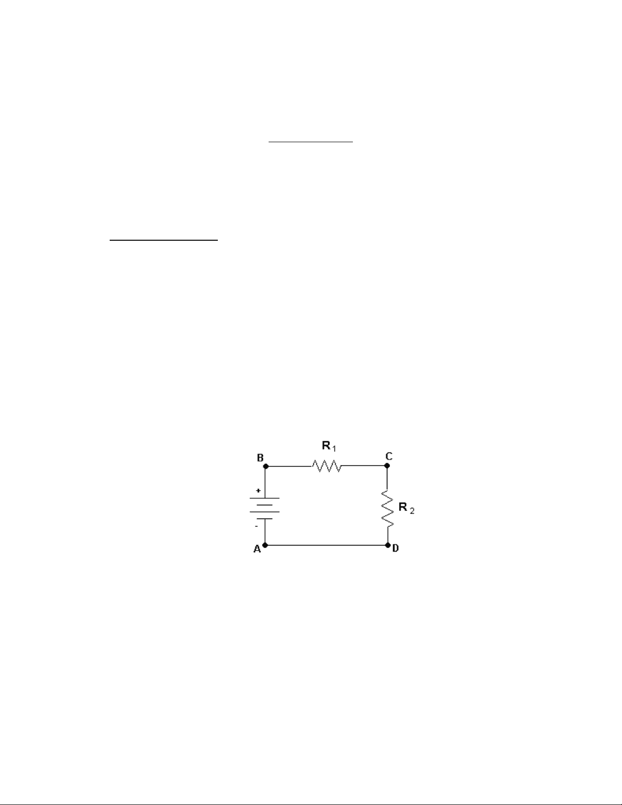
As an example, consider a circuit consisting of a voltage source V and two resistors R 1 and R 2 in series.
Start from the negative side of the voltage source and traverse the circuit clockwise.
- voltage gain VB-VA = V (voltage of the source)
- voltage loss VC-VB = -IR 1 (voltage drop across R 1 )
- voltage loss VA-VC = -IR 2 (voltage drop across R 2 )
Kirchhoff's loop law states that
V-IR 1 -IR 2 = 0
Then V = IR 1 + IR 2 V = I(R 1 + R 2 )
The equivalent resistance of R 1 and R 2 in series is
V/I = R 1 + R 2 = Rs
In general, if there are n resistors in series, then the equivalent resistance is given by
Rs = R 1 + R 2 + R 3 + ......... + Rn
B. Kirchhoff's Point Law
The conservation of electric charge, when applied to circuits, gives Kirchhoff's point of law: The net current flowing into a junction equals the net current flowing out.
As an example, consider a circuit consisting of a voltage source connected to two resistors in parallel.
Kirchhoff's current point states that:
I = I 1 + I 2
Kirchhoff's loop law applied to the two loops above states that
V = I 1 R 1 and V = I 2 R 2
The equivalent resistance of R 1 and R 2 in parallel is
V/I = V/(I 1 + I 2 ) = 1/(1/R 1 + 1/R 2 )
= (R 1 R 2 )/(R 1 + R 2 ) = Rp
In general, if there are n resistors in parallel, then the equivalent resistance is given by
1/Rp = 1/R 1 + 1/R 2 + ……………………..+ 1/Rn
- Remove the digital milliammeter from the circuit and switch it to an appropriate voltage range. Measure the voltages V 1 , V 2 , V 3 across the three resistors. For example, the diagram below shows the measurement of V 2.
Verify Kirchhoff's loop law: V 1 + V 2 + V 3 = 12 volts.
- Compute the voltage drops across the three resistors by using the voltage divider equations:
V 1 = 12 V(R 1 /Rs) V 2 = 12V(R 2 /Rs) V 3 = 12V(R 3 /Rs)
B. 1. Connect the three resistors in parallel, as shown.
Measure the resistance of this parallel combination with the digital ohmmeter. Compare this measurement with the value computed from the equivalent resistance equation for parallel resistors.
- Set up the circuit shown below and measure the total current I.
Compute the resistance of the parallel combination of resistors from V/I. Compute the resistance of the parallel combination of resistors from V/I.
- Put the digital milliammeter in each branch of the parallel resistor combination and measure the currents I 1 , I 2 , I 3. Verify Kirchhoff's current law:
I 1 + I 2 + I 3 = I
- Compute the three currents by using the current divider equations:
I 1 = I(Rp/R 1 ) I 2 = I(Rp/R 2 ) I 3 = I(Rp/R 3 )
where Rp is the equivalent resistance of the parallel combination.
C. Resistors in a Series and Parallel Combination
- Connect the three resistors as shown below.
\
Measure the resistance of this combination with the digital ohmmeter. The equivalent resistance of this combination is given by:
1/Req. = 1/R 1 + 1/(R 2 +R 3 )
Use this equation to compute Req and compare with the measured value.
- Set up the circuit shown below.
Compute the current delivered by the battery using I = V/Req.
Using the digital milliammeter measure I, I 1 , I 2 , and I 3. Switch the meter to an appropriate voltage range and measure V 1 , V 2 , and V 3.
Data Sheet - Experiment 2 Name______________________________
Section # ____________
A. Resistors in Series
- Measured values of the three resistors
R 1 = kΩ R 2 = kΩ R 3 = kΩ
- Measured value of the series combination
Rs(measured) = kΩ
- Computed value of the series combination using V/I
I = mA. (12 V.)/I = kΩ
- Measured values of V 1 , V 2 , V 3
V 1 = volts V 2 = volts V 3 = volts
V 1 + V 2 + V 3 = volts
- Computed values of V 1 , V 2 , V 3
V 1 = volts V 2 = volts V 3 = volts
B. Resistors in Parallel
- Measured value of the parallel combination
Rp (measured) = kΩ
Computed value of the parallel combination
Rp (computed) = kΩ
- Computed value of the parallel combination using V/I
I = mA. (12 V.)/I = kΩ
Measured values of V 1 , V 2 , V 3
V 1 = Volts V 2 = Volts V 3 = Volts
What relations do you see between these voltages?
Would any readings change if R 1 and R 2 were interchanged?
- Measured value of the combination
Req (measured) = kΩ
Computed value of the combination
Req (computed) = kΩ
- Computed value of the current.
I = mA
Measured values of I, I 1 , I 2 , I 3
I = mA I 1 = mA I 2 = mA I 3 = mA
What relations do you see between these currents?
Measured values of V 1 , V 2 , V 3
V 1 = Volts V 2 = Volts V 3 = Volts
What relations do you see between these voltages?
Would any readings change if R 1 and R 2 were interchanged?